Insertion Vortex Flow Meter
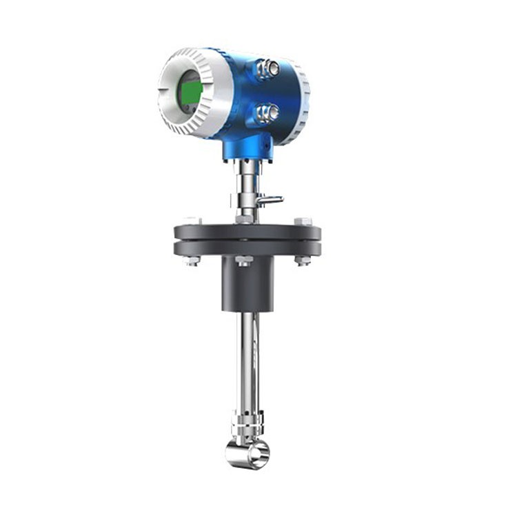
Insertion Vortex Flow Meter
Plug-in vortex flow meter Basic technical parameters:
◇Nominal diameter: 15~2500mm
◇Measuring medium: liquid, gas, steam
◇Medium temperature: -40~350℃ (capacitive type: -60~450℃)
◇Connection mode: flange card mounting type, flange type, plug-in type
◇Nominal pressure: 2.5MPa, 4.0MPa, 6.9MPa, 25MPa
◇Accuracy grade: 1.0 (liquid, gas), 1.5 (steam), 2.5 (plug-in)
◇Repeatability: ≤0.3%, 0.5%, 1.0%
◇Body material: stainless steel 304, stainless steel 316L
◇Load resistance: <750Ω
◇Power supply: 24VDC, 3.6V lithium battery
◇Output signal: pulse frequency, 4~20mADC, RS485, Hart protocol
◇Range of velocity: liquid 0.5~6m/s, gas 5~60m/s
◇Explosion-proof grade: iaⅡCT1—T6 intrinsically safe type (used with Zener safety barrier)
◇Protection level: IP65, IP67, IP68

More vortex flow meters

Flow range
| Instrument caliber(mm) | liquid | Gas | ||
Measuring range(m3/h) | Output frequency range(Hz) | Measuring range(m3/h) | Output frequency range(Hz) | |
15 | 0.3~5 | 24~400 | 4~20 | 352~1761 |
20 | 0.6~10 | 23~382 | 6~30 | 254~1273 |
25 | 1.2~16 | 21~320 | 8~55 | 161~1112 |
32 | 1.8~20 | 18~200 | 10~120 | 97~1172 |
40 | 2~40 | 10~190 | 27~205 | 134~1018 |
50 | 3~60 | 8~150 | 35~380 | 87~952 |
65 | 4~85 | 6~120 | 60~640 | 71~764 |
80 | 6.5~130 | 4.1~82 | 86~1100 | 54~696 |
100 | 15~220 | 4.7~69 | 133~1700 | 42~548 |
125 | 20~350 | 3.2~57 | 150~2000 | 26~346 |
150 | 30~450 | 2.8~43 | 347~4000 | 34~392 |
…… | ||||
300 | 95~2000 | 1.2~24 | 1360~18000 | 16~216 |
The installation method
(1) Insertion vortex flow meter installation as shown below, when pressure or temperature compensation is required, a separate pressure transmitter and temperature transmitter should be provided. The position of the pressure tapping hole is set at 3 to 5DN downstream of the sensor, and the diameter of the pressure tapping hole is 6 to 13 mm. The temperature measurement point is set at 6~8DN downstream of the sensor. (as shown in Figure 3 above)
(2) When the flanged-mounted vortex flowmeter is installed on the pipeline, in order to ensure accurate and reliable installation, the vortex flowmeter and the card-mounted flange can be bolted first, and then the clamped flange is welded. On the pipe. In order to prevent the vortex flowmeter from being damaged due to excessive temperature during welding, spot welding should be performed first, then the vortex flowmeter should be removed and then welded.
(3) In order to facilitate maintenance and inspection, a bypass pipe may be provided, which is installed on the vortex flowmeter and outside of the downstream straight pipe section to prevent it from affecting the measurement of the vortex flowmeter.
(4) The installation of the anti-fall type vortex flowmeter shall be carried out in accordance with the relevant provisions of GB383.15-2000 “Electrical Equipment for Explosive Gas Atmospheres”, Part 15: “Electrical Installation of Hazardous Locations (Excluding Coal Mines)”.
Payment Terms
1.Loading Port: Shanghai China
2. Samples Leading Time: 3-7 working days
3. Delivery Time: Within 7-15 days after payment
4.Payment: T/T, Western Union