Turbine Flow Meter Manufacturers
Turbine Flow Meter Manufacturers
2. Type: integrated type, pulse type (can be equipped with flowmeter and calculator, and can also be connected to control equipment)
3. Output mode: pulse, 4~20Ma, RS485 communication
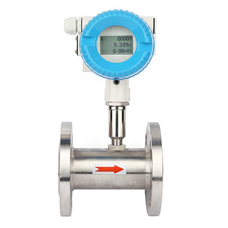
1.Introduce:
Turbine flow meters are devices used to measure the flow of liquids. They are commonly used in industrial and commercial environments where precise measurement of fluid flow is required. These flow meters work by measuring the rotational speed of a turbine or propeller placed in the fluid stream.
Henan Junyuan turbine flowmeter manufacturer specializes in the design, development and production of flow equipment. Advanced technology and engineering principles are used to ensure the instrument is highly accurate, reliable and efficient. We, as a manufacturer, offer a range of flow meters that can be customized to meet the specific needs of our customers.
|
|
|
|
|
|


2. Structural features and working principle:
*Structural features:
The sensor is a thrust type of hard alloy bearing, which not only ensures the accuracy and improves the wear resistance, but also has the advantages of simple structure, strong and easy disassembly.
*Working criteria:
When the fluid flows through the sensor housing, due to the angle between the impeller blades and the flow direction, the fluid blades generate the impact of rotational torque, which overcomes the frictional torque and fluid resistance. After the knife speed is stable, the moment is balanced. Magnetic vane, in the magnetic field of the signal detector (composed of permanent magnets and coils), the rotating blade cuts the line and periodically changes the magnetic flux of the coil, thereby inducing an electric pulse signal coil at the end, and the signal is amplified and shaped by the amplifier to form A continuous rectangular pulse wave with a certain amplitude can be transmitted to the display instrument remotely to display the instantaneous flow or volume of the fluid. Within a certain flow range, the pulse frequency f is proportional to the instantaneous flow Q of the fluid flowing through the sensor, and the flow equation is: 
Type:
f —— pulse frequency (Hz)
k —— he instrument coefficient of sensor 1 / m3, given by the check list. If [1 / L] as the unit
Q— fluid transient flow (working conditions) m3 / h
3600 —— conversion factor
Coefficient of each sensor of the instrument in the calibration certificate will be completed by the manufacturer, set into the display instrument of form a complete set of k value, can show the instantaneous flow and cumulative total.
3.Basic parameters and technical performance table:
Product model and sign | instruction | |||||
| LWGY□ | caliber | □ | □ | □ |
|
type | LWGY |
|
|
|
| Basic, + 12 V/24V power supply, pulse output, high level 8 v or higher Low level 0.8 V or less |
LWGYA |
|
|
|
| Two wire system 4 ~ 20 ma output current, far eastone – type | |
LWGYB |
|
|
|
| Battery type display at the scene | |
LWGYC |
|
|
|
| The scene shows two wire / 4 ~ 20 ma current output | |
Nominal diameter | DN4 |
|
|
| 4 mm, ordinary turbine flow range of 0.04 ~ 0.04 m3 / h Wide-range turbine is 0.04 ~ 0.4 m3 / h | |
DN6 |
|
|
| 6 mm, ordinary turbine flow range of 0.1 ~ 0.1 m3 / h Wide-range turbine is 0.06 ~ 0.6 m3 / h | ||
DN10 |
|
|
| 10 mm, ordinary turbine flow range of 0.2 ~ 1.2 m3 / h Wide-range turbine is 0.15 ~ 1.5 m3 / h | ||
DN15 |
|
|
| 15 mm, ordinary turbine flow range 0.6 ~ 6 m3 / h Wide-range turbine is 0.4 ~ 8 m3 / h | ||
DN20 |
|
|
| 20 mm ordinary turbine flow range 0.8 ~ 8 m3 / h | ||
DN25 |
|
|
| 25 mm, ordinary turbine flow range 1 ~ 10 m3 / h Wide-range turbine is 0.5 ~ 10 m3 / h | ||
DN40 |
|
|
| 40 mm, ordinary turbine flow range 2 ~ 20 m3 / h Wide-range turbine for 1 ~ 20 m3 / h | ||
DN50 |
|
|
| 50 mm, ordinary turbine flow range 4 ~ 40 m3 / h Wide-range turbine for 2 ~ 40 m3 / h | ||
DN80 |
|
|
| 80 mm, ordinary turbine flow range 10 ~ 100 m3 / h Wide-range turbine is 5 ~ 100 m3 / h | ||
DN100 |
|
|
| 100 mm, ordinary turbine flow range from 20 to 200 m3 / h Wide-range turbine is 10 ~ 200 m3 / h | ||
DN150 |
|
|
| 150 mm, ordinary turbine flow range 30 ~ 300 m3 / h Wide-range turbine for 15 ~ 300 m3 / h | ||
DN200 |
|
|
| 200 mm, ordinary turbine flow range of 80 ~ 800 m3 / h Wide-range turbine is 40 ~ 800 m3 / h | ||
Explosion proof |
|
|
| No mark for the explosion proof type | ||
B |
|
| explosion proof type | |||
accuracy grade | A |
| Precision±0.2grade | |||
B |
| Precision±0.5grade | ||||
Turbine flow type | A | Wide-range turbine | ||||
B | Ordinary turbine | |||||
DN4-DN40——The diameter of the sensor is threaded connection, the maximum working pressure is 6.3Mpa;
DN15-DN200 caliber flange connection sensor, maximum working pressure 4.0Mpa.
Straight pipe for DN4-DN10 caliber sensor, front and rear filters.
DN15 or more straight pipes can be equipped with sensors before and after.
DN15-DN40——The sensor diameter can be made into flange connection, thread connection, and clamp connection.
* Medium temperature: -20~+150℃.
* Temperature: -20~+55℃.
* Power supply voltage: 12v/24v, current: below 10ma.
*Output voltage amplitude, high level 8V or higher, low level 0.8V or less.
*Transmission distance, the distance from the sensor to the display instrument can reach 1000 meters.
4. Installation, use and adjustment:
The installation method of the sensor adopts threaded or flange connection according to different specifications. The installation method is as shown in the figure:

Remark:1. The filter, 2. Straight pipe before, 3. The impeller ,4. The impeller preamplifier, 5. Case ,6. After the straight pipe

Remark:1. The compression ring,2. The bolt 4 x 14 ,3. The washer,4. gasket sealing gasket, 5. Wire 1Cr18Ni9Ti – 0.8 x 2.5,6. Screen pack, 7.base

Remark:1. Case ,2. Guide before a ,3. impeller, 4. The impeller leads to a, 5. After preamplifier

Remark:1. The ball bearing, 2 ball bearing guide before a, 3. The flange,4 flange shell ,5. Preamplifier, 6. Impeller ,7. bearing,8. Bearing axis
5.Sensor production workshop:
|
|


6.FAQ:
1. Q: Are you a manufacturer of turbine flowmeters?
A: Yes! We have more than 20 years of manufacturing experience, the factory was established in 2002, and our international trade department was established in 2018.
2. Q: Do you accept customization?
A: Yes. We can customize products according to the different needs of customers.
3. Q: Do you support sample service? What is the MOQ?
A: Yes, our MOQ is 1PCS.
4. Q: What is your payment method?
A: We support TT payment, online credit card payment, Western Union payment, cross-border RMB payment, LC payment.