Turbine Type Flow Meter Working Principle
Turbine Type Flow Meter Working Principle

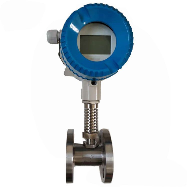
Turbine type flow meter working principle
liquid turbine flow meter is used for volumetric total flow and/or flow rate measurement and has a relatively simple working principle.
As fluid flows through the turbine meter, it impinges upon turbine blades that are free to rotate about an axis along the center line of the turbine housing.
The angular (rotational) velocity of the turbine rotor is directly proportional to the fluid velocity flowing through the turbine.
The resulting output is taken by an electrical pickoff(s) mounted on the flow meter body.
Measurable medium
Measuring medium flow rate, instrument range and caliber When measuring general medium, the full-scale flow of the turbine flowmeter can be selected within the range of measuring medium flow rate 0.5-12m/s, and the range is relatively wide. The gauge size (caliber) selected is not necessarily the same as that of the process pipeline, and should be determined according to whether the measuring flow range is within the flow rate range.
That is, when the pipeline flow rate is too low to meet the requirements of the flow meter or when the measurement accuracy cannot be guaranteed at this flow rate, the meter diameter needs to be reduced, so that the flow rate in the pipeline is high and satisfactory measurement results are obtained.
Technical parameter
| Product name | Turbine flow meter |
Nominal Diameter(mm) | DN4-DN200mm |
Medium | Water,diesel,oil,fuel,hydraulic oil,gas ,LPG,etc |
Accuracy Class | The standard type is 1%,Customized for 0.5% and 0.2% |
Instrument material | SS304; SS316; etc. |
Medium Temperature | Medium:-20~120℃ |
Connection | Thread,Flange, Tri-clamp |
Signal Output | 4-20mA or pulse output |
Supply Power | AC220V, DC12-24V or Lithium cell Batery |
Signal Line Interface | Internal thread M20×1.5 |
Explode-proof Class | ExdIIBT6 |
Protection Class | IP65 |
Keywords | turbine flow meter for water juice |
Turbine flow meter type

Installation
1. Installation location
The flowmeter should be installed horizontally, and the arrow indicating the flow direction on the sensor during installation should match the flow direction of the fluid.
2. Installation place
The flowmeter should work under the condition that the temperature of the liquid being measured is -20~+120℃, and the relative humidity of the environment is not more than 80%. From the perspective of easy maintenance, it should be installed in a place where it is easy to disassemble and replace and avoid pipe vibration or pipe stress. Taking into account the protection of the amplifier, it should be avoided as far as possible from strong thermal radiation and radioactivity. At the same time, the influence of strong external electromagnetic on the detection coil must be avoided. If it cannot be avoided, a shielding cover should be installed on the amplifier of the sensor, otherwise the interference will seriously affect the normal operation of the display instrument.

When tuning and shrinking: L=15D when single elbow joint: L=20D
For double elbow joints: L=25D (one plane) L=30D (two planes)
For right-angle elbow joint: L=40D
When there is a straight stop valve: L=20D (valve fully open) L=50D (valve half open)
In addition. In order to effectively control the eddy current and improve the measurement accuracy, a rectifier composed of a bunch of tubes can be transferred into the straight pipe section of the upstream part. After the French upper rectifier, the length of the straight pipe section is (10~20)D.
(2) There are impurities in the fluid, which will affect the operation of the sensor. In order to improve the life of the sensor, a filter with a mesh size of 3-9 days/cm2 should be installed on the pipeline in front of the sensor. In general, the meshes with a large diameter are sparse, and the meshes with a small diameter are dense. In order to ensure the normal operation of the sensor, the filter should also be selected according to the actual usage.
(3) When welding the sensor inlet flange, it must be noted that there is no protruding part in the pipe. When connecting the inlet flange, the outer circumference of the two flanges is completely anastomosed, and the ring cannot be exposed in the pipe. The eccentric reducer will cause uneven flow velocity distribution, so it cannot be used.
(4) In order to ensure the need for maintenance under the working diameter, a cut-off valve (stop valve) should be installed on the pipeline before and after the transmitter, and a bypass pipeline should be installed.
The flow control valve should be installed downstream of the sensor. When the sensor is used, the upstream shut-off valve must be fully opened to avoid turbulence in the upstream part of the fluid.
(5) When the flow through the sensor is too large (exceeding the upper limit of the flow range), the bearing will wear out due to the high speed surface. Therefore, when an excessive flow is expected, the flow control valve located in the downstream part can adjust the flow.
(6) Because the gas in the pipeline will bring large errors to the measurement of the sensor, when installing, pay special attention to the situation where gas is mixed in the liquid to be measured, especially for the measurement of light liquid media. There is an air separator.
(7) When installing the sensor in a new pipe, in order to avoid impurities in the pipeline from entering the sensor, it is recommended to replace the sensor with an empty pipe after running for a period of time, and then replace the sensor after confirming that the impurities have been drained.