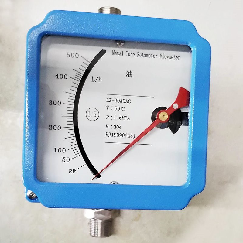
Variable Flow Meter

Variable Flow Meter
Diameter (mm) | Flow range | Pressure loss KPa | Accuracy level | ||||
15 | Water L/h | Air m3/h | Water | Air | |||
Normal temperature type | Anticorrosive | Normal temperature type | ,Anticorrosive | ||||
2.5—25 | 2.5—-25 | 0.07–0.7 | 0.07—0.7 | 6.5 | 7.1 | 1.5 | |
4.0—40 | 4.0—40 | 0.11—1.1 | 0.11—1.1 | 7.2 | |||
3.6—63 | 6.3—63 | 0.18—1.8 | 0.18—1.8 | 6.6 | 7.3 | ||
10—100 | 10—100 | 0.28—2.8 | 0.28—2.8 | 7.5 | |||
16—-160 | 16—160 | 0.4—4.0 | 0.4—4.0 | 6.8 | 8.0 | ||
25—-250 | 25—-250 | 0.7—7.0 | 0.7—-7.0 | 7.2 | 10.8 | ||
40—400 | 40—400 | 1.0—10 | 1.0—-10 | 8.6 | 10.0 | ||
63—630 | ——- | 1.6—16 | ——— | 11.1 | 14.0 | ||
25 | 100—1000 | 63—630 | 3.0—30 | 1.6—-16 | 7.0 | 7.7 | |
160—1600 | 100—1000 | 4.5—45 | 3.0—30 | 8.0 | 8.8 | ||
250—2500 | 160—-1600 | 7.0—-70 | 4.5—-45 | 10.8 | 12.0 | ||
400—4000 | 250—2500 | 11—110 | 7.0—–70 | 15.8 | 19.0 | ||
50 | 630–6300 | 400—4000 | 18—180 | 11—–110 | 8.1 | 8.6 | |
1000—10000 | 630—6300 | 25—-250 | 18—-180 | 11.0 | 10.4 | ||
1600—16000 | 1000—10000 | 40—-400 | 25—-250 | 17.0 | 15.5 | ||
80 | 2500—25000 | 1600—16000 | 60—600 | 40—-400 | 8.1 | 8.0 | |
4000—40000 | 2500–25000 | 100—-1000 | 60—600 | 9.5 | 13.0 | ||
100 | 6300—63000 | 4000—40000 | 200—2000 | 100—-1000 | 10.0 | 11.0 | |
10000—100000 | ——- | 300—-3000 | ——– | ||||
Parameter
| Ange of flow | Liquid 1.0~150000L/h |
Gas 0.03~4000m3/h | |
Measure Ratio | 101,201(special) |
Precision | Grade 1.5, Grade 1.0 (special) |
Pressure rating | DN15~DN50:4.0MPa;DN80~DN200:1.6MPa |
DN15~DN50:25MPa;DN80~DN200:16MPa | |
Medium temperature | Standard:-80℃ ~+200℃ ,PTFE: 0℃ ~+85℃,high temperature:400℃ |
Power supply | Standard: 24VDC(12~36VDC); AC type: 85~265VAC 50Hz; Battery type:3.6V@4AH |
Output signal | Collector open circuit output(max 100mA@30VDC internal impedance 100Ω |
Relay output(max 5A@250VAC) | |
Environmental temperature | Liquid crystal type:-30℃ ~85℃ |
Storage requirement | Temperature:-40℃ ~85℃ humidity:≤85% |
Connection mode | Flange connecting. Flange standard :GB/T9119-2000; User’s appointment allowed |
Cable interface | M20×1.5 |
Housing protection grade | Ip65 |
Mark of explosion-proof | Intrinsic safety type:ExiaIICT6 explosion-proof type:ExdIICT6 |
Pressure loss | 7kPa~70kPa |
Viscosity of medium | DN15:η<5mPa.s DN25:η<250mPa.s DN50~DN150:η<300mPa.s |
Contact material | R1:304,1Cr18Ni9Ti; Ro:316,0Cr18Ni12Mo2Ti; RL:316L,00Cr17Ni14Mo2Ti; |
Ti:Titanium alloy; Rp:PTFE lining |
Installation requirements
In the picture: 5XDN and 250 are front and rear straight pipe segments, 100 is reserved for excitation filter.
Precautions for installation:
1. Before installation of the Variable Flow Meter, the process pipeline should be purged to prevent the stranded ferromagnetic substances in the pipeline from adhering to the instrument.It affects the performance of the meter and can even damage the meter.If not, a magnetic filter should be installed at the inlet of the meter.The affected instrument itself does not participate in the air sweep before production, so as not to damage the instrument.
2. Before the instrument is installed, all package should be removed and checked for transportation damage, and the shell should be opened to remove the filling of the fixed pointer.
3. The installation of the Variable Flow Meter can be divided into vertical installation and horizontal installation. In the case of vertical installation, the Angle between the center vertical line and the plumb line should be less than 2; in the case of horizontal installation, the Angle between the horizontal center and the horizontal leader should be less than 2.
4. The upstream and downstream pipes of the instrument should be the same as the diameter of the instrument, and the connecting flange or thread should be matched.The length of the straight pipe section on the instrument should be 5 times of the nominal diameter of the instrument, and the length of the downstream straight pipe section should be no less than 250mm.
5. Because the instrument is through the magnetic Shao to transfer signals, so in order to ensure the performance of the instrument. No ferromagnetic material is allowed to exist at least 10m around the installation.
6. Gauges that measure gases are calibrated at a particular pressure.If gas is vented directly into the atmosphere at the outlet of the meter, it will create pressure drop at the float and cause distortion. If this happens, a valve should be installed at the outlet of the meter.
7. Gauges installed in pipelines shall not be subjected to pressure, and the inlet and outlet of the instrument shall be properly supported by pipes to minimize the stress of the instrument.
8. When installing PTFE-lined instruments, special care should be taken, as PTFE will deform under pressure.So the flange nut should not be screwed too tightly at will.
9. With liquid crystal display instrument, installation should try to avoid direct sunlight display, thereby reducing the life of the liquid crystal display
10. Low temperature medium measurement, need to choose the jacket type.
FAQ
1. How about your delivery time?
Generally, it will take 5 to 10 days after receiving your advance payment. The specific delivery time depends on the items and the quantity of your order.
2. Can you produce according to the samples?
Yes, we can produce by your samples or technical drawings. We can build the molds and fixtures.
3. What’s your payment method?
Paypal, T/T, L/C, Western Unions, are available.
4.How do you pack your products?
We pack the goods in wooden cases or according to customer’s requirement.
5.How can I order a sample?
You can talk to customer service and he will help you.
6.What is the warranty for your product ?
Warranty: 1 years.